Printable Breadboard Grid Paper (Free PDF)

The dot pattern of a solderless breadboard at true 0.1 inch pitch, with lettered rows, numbered columns and the power rails marked, for planning a circuit before you build it.
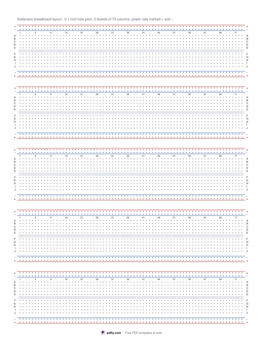
Printable breadboard layout paper with power rails, lettered rows and numbered columns
Layout
Paper size
Edit free online

Free · no watermark · no sign-up for your first 20 downloads a day

Working a circuit out on paper first saves pulling jumper wires out later. This sheet prints five solderless breadboards down a page, each drawn the way the real thing is laid out: a pair of power rails along the top, rows A to E, the centre channel, rows F to J, and a second pair of rails along the bottom. The rails are marked plus and minus at both ends and drawn in red and blue, and the columns are numbered every five so you can transfer your sketch to the board hole by hole.

The dots sit at 0.1 inch - 2.54 mm - which is the pitch of every breadboard and of the pins on a DIP chip, so a 16-pin package straddling the channel spans eight columns on the paper exactly as it does on the board. US Letter gives 73 columns per board and A4 gives 71, with five boards either way. Draw the chips as rectangles, mark the jumpers between columns, and the layout you end up with is the one you can build.

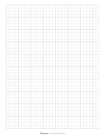
The second layout turns the whole page into a plain 0.1 inch hole matrix for perfboard and point-to-point work, with every tenth hole drawn larger and inch markers down the left edge and across the top - 73 by 96 holes on US Letter. Both versions derive their spacing from the real inch and are centred with equal margins, so printed at 100% a ruler agrees with the pitch.

How to use it

  1. 1

    Choose the layout

    Solderless breadboards with rails and lettered rows, or a plain perfboard hole matrix for point-to-point wiring.

  2. 2

    Pick the paper size

    US Letter or A4 - the dot grid is counted and centred again for the sheet you choose.

  3. 3

    Print at actual size

    In the print dialog choose "Actual size" or 100% instead of "Fit to page", so every measurement on the sheet comes out exactly as labeled.

  4. 4

    Sketch the circuit

    Draw the chips across the centre channel, mark the jumpers, and use the column numbers to copy the layout onto the real board.

Frequently asked questions

Yes. There is no watermark and no sign-up for your first 20 downloads each day; after that a free account keeps downloads going. You may print the file as often as you like for personal, school or business use.
Yes, 0.1 inch or 2.54 mm, set from the real inch. Printed at 100% it matches a breadboard and the pin spacing of a DIP chip, so a ruler on the page agrees.
Five boards per page, 73 columns each on US Letter and 71 on A4. Each board has rows A to E and F to J either side of the centre channel.
The power rails: red for the positive rail and blue for the negative, marked with a plus and a minus at both ends, exactly as they are printed on a breadboard.
Stripboard, perfboard and point-to-point layouts. It turns the page into a plain 0.1 inch hole matrix - 73 by 96 holes on US Letter - with every tenth hole marked and inch rulers along two edges.
Yes. Open the PDF in an annotation app such as GoodNotes, Notability or Xodo and draw on it with a stylus; the grid stays crisp at any zoom because it is vector, not an image.

More free templates

Work with your PDF